Timers
Hoeveel PWM pinnen heeft een Arduino Nano?
Vanwaar komt deze restrictie?
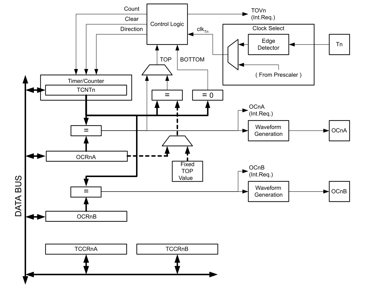
Timer 0 Blok Diagramma
- Veel instellingen
- Veel registers
- Hoger complexiteit
TC0 Control Register A
- Instellen van Compare Output Mode
- COM0xn
- Channel A (Arduino Pin 5)
- Channel B (Arduino Pin 6)
- Instellen van Waveform Generation Mode
- WSG[1:0]
- Normal
- Fase Correct PWM
- CTC
- Fast PWM

TC0 Control Register B
- FOCBx
- Compatibiliteit met toekomstig devices
- Instellen van Waveform Generation Mode
- WSG[2]
- Clock Select en Prescaler
- CS[2:0]

Waveform Generation Mode
- Values
- BOTTOM = 0x0
- MAX = 0xFF
- TOP = MAX || OCR0x
- WSG[2]
- Frequentie Manipulatie
- Niet direct gebruikt

WGM: Normal Mode
IF COUNTER == MAX
  COUNTER = BOT
  SET INTERRUPT FLAG
ELSE COUNTER++
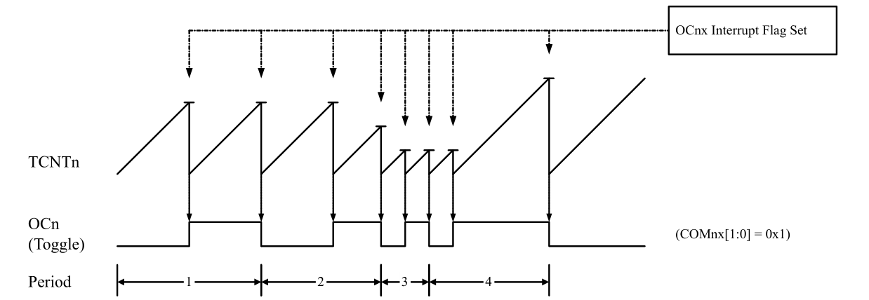
WGM: Clear Timer on Compare Match (CTC)
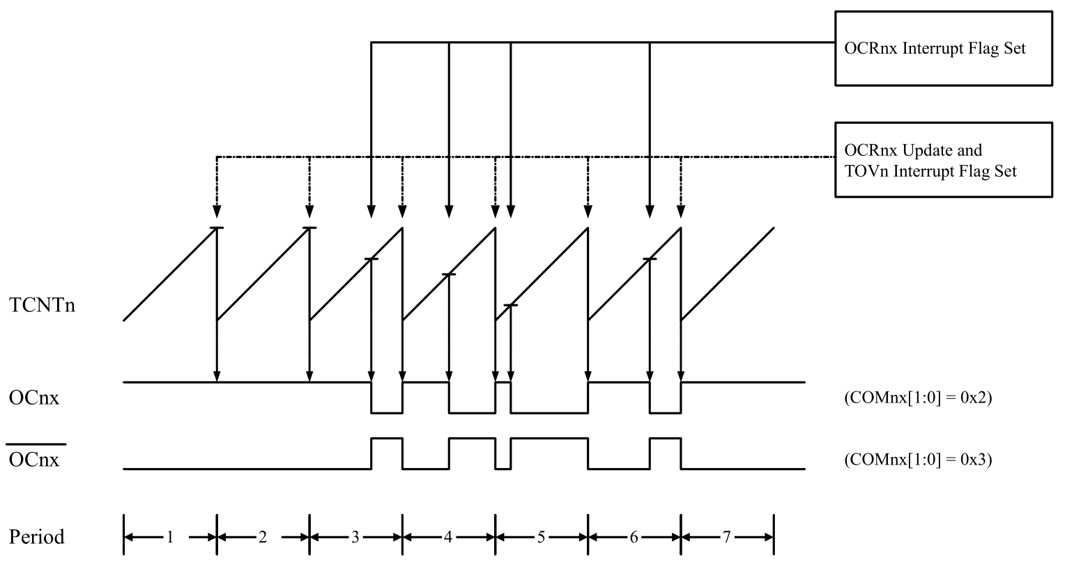
WGM: Fast PWM
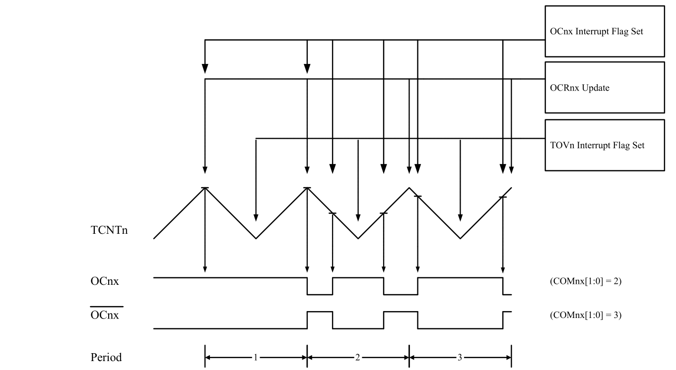
WGM: Phase Correct PWM
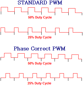
Fast PWM vs Phase Correct PWM
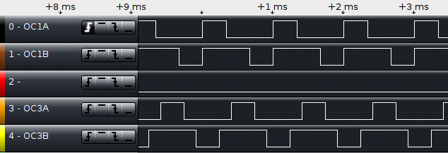
Compare Output Mode (Normal Mode)

Compare Output Mode (Fast PWM)

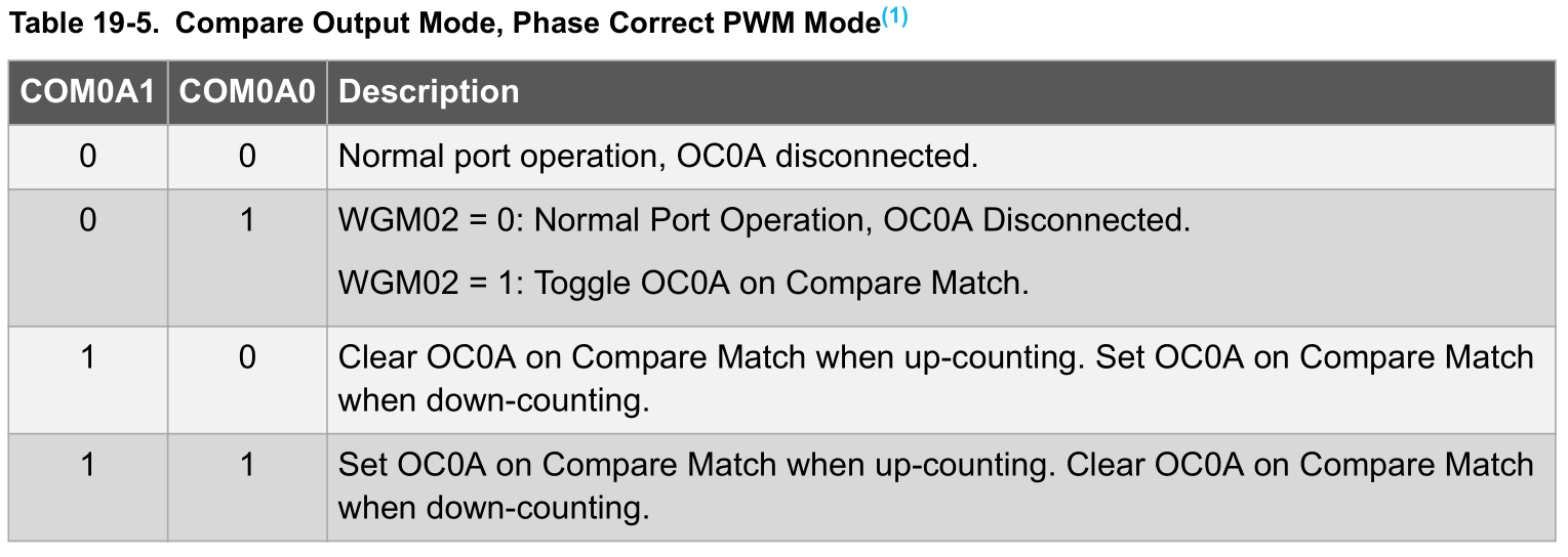
Compare Output Mode (Phase Correct PWM)
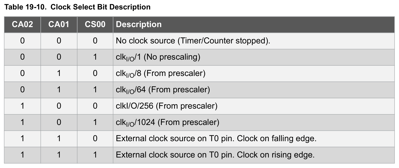
Clock Select / Prescaler
TC0 Interrupt Mask Register
- Enablen van Events
- Compare Match Interrupts
- Timer Overflow Event

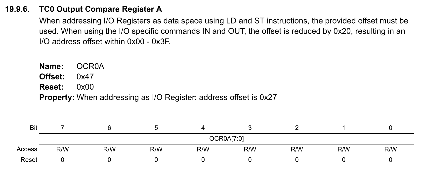
TC Output Compare Register
- Waarde om te vergelijken
- 0 - 255
- Een per channel
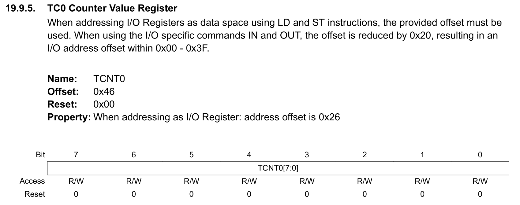
TC 0 Counter Value Register
- Huidige waarde van Timer
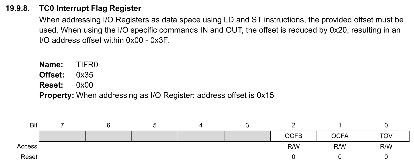
TC 0 Interrupt Flag Register
- Is interrupt getriggerd?
- Compare event
- Overflow event
Implementatie op de Arduino
Init Functie
void init()
{
	sei();
	sbi(TCCR0A, WGM01);
	sbi(TCCR0A, WGM00);

	// set timer 0 prescale factor to 64
	sbi(TCCR0B, CS01);
	sbi(TCCR0B, CS00);
	// enable timer 0 overflow interrupt
	sbi(TIMSK0, TOIE0);

	TCCR1B = 0;

	// set timer 1 prescale factor to 64
	sbi(TCCR1B, CS11);
	sbi(TCCR1B, CS10);
	// put timer 1 in 8-bit phase correct pwm mode
	sbi(TCCR1A, WGM10);

	// set timer 2 prescale factor to 64
	sbi(TCCR2B, CS22);

	// configure timer 2 for phase correct pwm (8-bit)
	sbi(TCCR2A, WGM20);
AnalogWrite
void analogWrite(uint8_t pin, int val)
{
	pinMode(pin, OUTPUT);
	if (val == 0)
	{
		digitalWrite(pin, LOW);
	}
	else if (val == 255)
	{
		digitalWrite(pin, HIGH);
	}
	else
	{
		switch(digitalPinToTimer(pin))
		{

			#if defined(TCCR0A) && defined(COM0A1)
			case TIMER0A:
				// connect pwm to pin on timer 0, channel A
				sbi(TCCR0A, COM0A1);
				OCR0A = val; // set pwm duty
				break;
			#endif

			#if defined(TCCR0A) && defined(COM0B1)
			case TIMER0B:
				// connect pwm to pin on timer 0, channel B
				sbi(TCCR0A, COM0B1);
				OCR0B = val; // set pwm duty
				break;
			#endif

			#if defined(TCCR1A) && defined(COM1A1)
			case TIMER1A:
				// connect pwm to pin on timer 1, channel A
				sbi(TCCR1A, COM1A1);
				OCR1A = val; // set pwm duty
				break;
			#endif

			#if defined(TCCR1A) && defined(COM1B1)
			case TIMER1B:
				// connect pwm to pin on timer 1, channel B
				sbi(TCCR1A, COM1B1);
				OCR1B = val; // set pwm duty
				break;
			#endif

			#if defined(TCCR1A) && defined(COM1C1)
			case TIMER1C:
				// connect pwm to pin on timer 1, channel B
				sbi(TCCR1A, COM1C1);
				OCR1C = val; // set pwm duty
				break;
			#endif

			#if defined(TCCR2) && defined(COM21)
			case TIMER2:
				// connect pwm to pin on timer 2
				sbi(TCCR2, COM21);
				OCR2 = val; // set pwm duty
				break;
			#endif

			#if defined(TCCR2A) && defined(COM2A1)
			case TIMER2A:
				// connect pwm to pin on timer 2, channel A
				sbi(TCCR2A, COM2A1);
				OCR2A = val; // set pwm duty
				break;
			#endif

			#if defined(TCCR2A) && defined(COM2B1)
			case TIMER2B:
				// connect pwm to pin on timer 2, channel B
				sbi(TCCR2A, COM2B1);
				OCR2B = val; // set pwm duty
				break;
			#endif
			case NOT_ON_TIMER:
			default:
				if (val < 128) {
					digitalWrite(pin, LOW);
				} else {
					digitalWrite(pin, HIGH);
				}
		}
	}
}
const uint8_t PROGMEM digital_pin_to_timer_PGM[] = {
	NOT_ON_TIMER, /* 0 - port D */
	NOT_ON_TIMER,
	NOT_ON_TIMER,
	TIMER2B, //pin 3
	NOT_ON_TIMER,
	TIMER0B, //pin 5
	TIMER0A, //pin 6
	NOT_ON_TIMER,
	NOT_ON_TIMER, /* 8 - port B */
	TIMER1A, //pin 9
	TIMER1B, //pin 10
	TIMER2A, //pin 11
	NOT_ON_TIMER,
	NOT_ON_TIMER,
	NOT_ON_TIMER,
	NOT_ON_TIMER, /* 14 - port C */
	NOT_ON_TIMER,
	NOT_ON_TIMER,
	NOT_ON_TIMER,
	NOT_ON_TIMER,
};
Delay
void delay(unsigned long ms)
{
	uint32_t start = micros();

	while (ms > 0) {
		yield();
		while ( ms > 0 && (micros() - start) >= 1000) {
			ms--;
			start += 1000;
		}
	}
}
unsigned long micros() {
	unsigned long m;
	uint8_t oldSREG = SREG, t;

	cli();
	m = timer0_overflow_count;
	t = TCNT0;

	if ((TIFR0 & _BV(TOV0)) && (t < 255))
		m++;
	SREG = oldSREG;

	return ((m << 8) + t) * (64 / clockCyclesPerMicrosecond());
}
volatile unsigned long timer0_overflow_count = 0;
volatile unsigned long timer0_millis = 0;
static unsigned char timer0_fract = 0;

ISR(TIMER0_OVF_vect)
{
	unsigned long m = timer0_millis;
	unsigned char f = timer0_fract;

	m += MILLIS_INC;
	f += FRACT_INC;
	if (f >= FRACT_MAX) {
		f -= FRACT_MAX;
		m += 1;
	}

	timer0_fract = f;
	timer0_millis = m;
	timer0_overflow_count++;
}
Hulp functies
#define clockCyclesPerMicrosecond() ( F_CPU / 1000000L )
#define clockCyclesToMicroseconds(a) ( (a) / clockCyclesPerMicrosecond() )
#define microsecondsToClockCycles(a) ( (a) * clockCyclesPerMicrosecond() )
// the prescaler is set so that timer0 ticks every 64 clock cycles, and the
// the overflow handler is called every 256 ticks.
#define MICROSECONDS_PER_TIMER0_OVERFLOW (clockCyclesToMicroseconds(64 * 256))

// the whole number of milliseconds per timer0 overflow
#define MILLIS_INC (MICROSECONDS_PER_TIMER0_OVERFLOW / 1000)

// the fractional number of milliseconds per timer0 overflow. we shift right
// by three to fit these numbers into a byte. (for the clock speeds we care
// about - 8 and 16 MHz - this doesn't lose precision.)
#define FRACT_INC ((MICROSECONDS_PER_TIMER0_OVERFLOW % 1000) >> 3)
#define FRACT_MAX (1000 >> 3)
Oefening #1
void setup()
{
  Serial.begin(9600);
  DDRD |= (1 << DDD3);
  TCCR2A |= (1 << COM2B1); //
  OCR2B = 255;
}
void loop()
{
  Serial.println(TCNT2);
}
Oefening #2
- Toggle een led mbv een timer event
- Configureer een led op pin D3
- Configureer led met registers
- Stel op Timer 2 het volgende in
- OVF event
- Fast PWM
- Prescaler op 1024